Using the transistor base in here: transistor.
I’m gonna talk about logic gates and some basic possibilities like adders, subtractors, multipliers, and dividers. The main idea in these basic posts is to trace the way to assembly instructions and so on.
These logic gates are the lowest level we can reach in hardware processing. Obviously, these instructions alone don’t create anything really meaningful, but the correct combination can create computers and processing machines of any type (except quantum computers, but we’re not gonna talk about them today)
So logic gates are simply a transistor sequence that creates properties (AND, OR, NAND, NOR, XOR and XNOR)
- The X in the name means “exclusively”, like in the OR gate that usually would accept 1|1, but with X it’ll only accept the 1|0 (the order of the factors doesn’t matter)
- The N means the opposite of the original logic gate output.
- At the bottom of the image there are some “grounds” that I recommend looking into in this explanation before continuing
- The +6V is the place where electricity comes from, and the out is where it comes out if the logic gate sustains the correct input (the input is just the electrical presence in A or B that’ll activate the transistor)
Transistor level approach:
- AND (The first input and the second simultaneously):
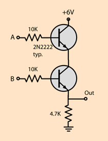
Figure 1 - AND gate (transistor level)
- OR (The first input, the second, or both):
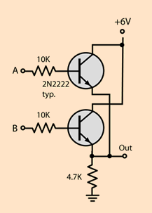
Figure 2 - OR gate (transistor level)
- NAND (The first input, the second, or none of them):
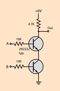
Figure 3 - NAND gate (transistor level)
- NOR (Both of them off):
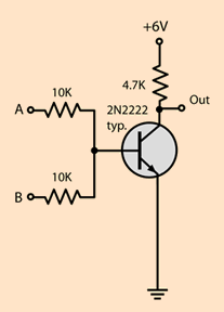
Figure 4 - NOR gate (transistor level)
Truth tables:
Figure 5 - Logic gate truth tables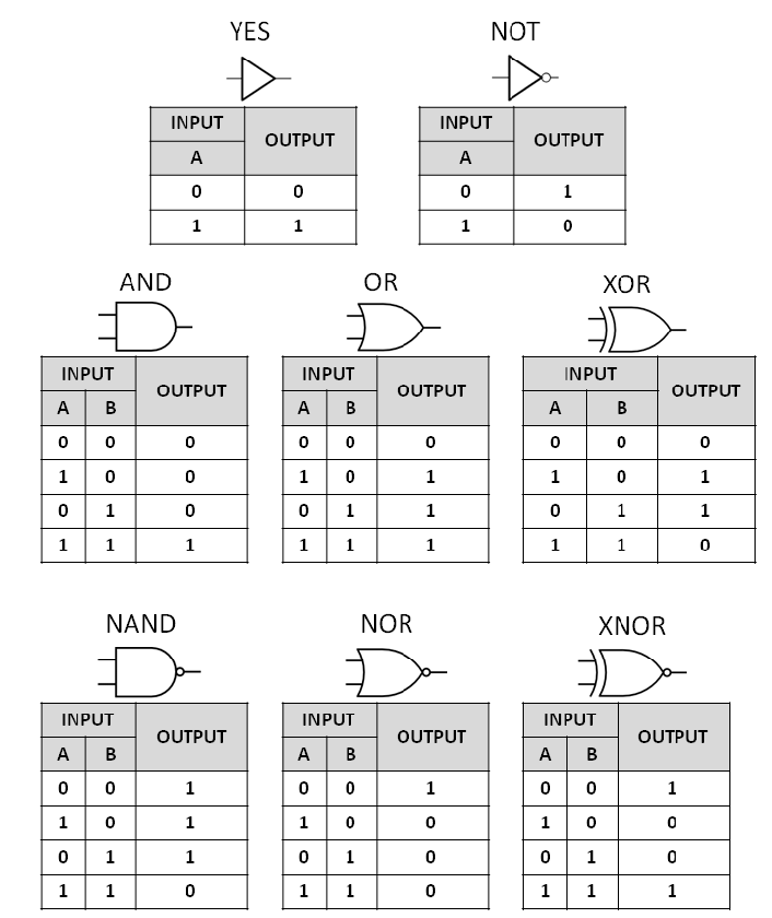
I didn’t put XOR and XNOR transistor-level images because they use the other basic gates and i think it’ll confuse more than help right now.
Now you might be thinking something like:
-“Why would I even have to know this”
And I tell you that this is the base of any normal computer (the quantum computer is the only different one that I can think of right now, but we’re not gonna talk about them today)
Now I’m gonna take a more practical approach with something more easily understandable, the adder:
Adder
- If you need some basic idea help in binary mathematics this site can help.
The adders use this logic gate setup (I’m gonna start using these images with the minimal representation of the logic gates, because it would become bothersome to use so much space with logic gates at transistor level):
Figure 6 - Full adder built from logic gates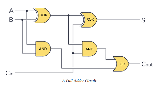
The adder receives 3 inputs, the binary of the first number, the second, and the “carry-in” (cin), but if it’s the first comparison the cin is ignored, because the carry-in is the carried number from the last operation, aka the COUT that appears at the end of the circuit. So, for a better visualization, this is the truth table:
Figure 7 - Adder truth table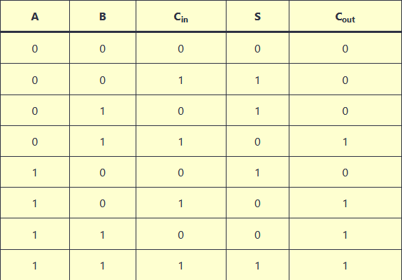
So, if we have 2 numbers, 1001 and 1000, the adder circuit will compare the far right number from both. In this case it’ll be 1 and 0, resulting in S = 1 and Cout = 0, creating the first bit of the output, which is S (1). With this, we conclude that the adder will be run for every bit we have in our sum operation. In this situation we have 2 numbers of 4 bits, so the adder is gonna be run 4 times to get the full output/result.
If you want to see some real implementation of this adder there is this incredible video
Subtractor
The subtractor uses the same base as the adder, but we have to think about some problems, for example, the negative numbers.
If we think about it directly, the binary number technically groups just positive numbers, so the solution in this case is to use the MSB (most significant bit) as a sign for positive (0) or negative (1). So, if the number is positive like 1010 (10 in decimal) it would be 01010, and the opposite would be 11010 (-10 in decimal).
There are also two types of circuits for subtractors, the full subtractor and the half subtractor, and they apply to different situations. The “full” has 3 inputs, so we can carry the output of the last run and so on for more complex operations, while the half is useful just for operations with 2 bits.
The logic circuit of the subtractor (the full one, because it’s more useful and interesting)
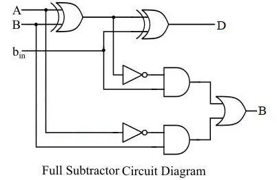
Figure 8 - Full subtractor logic circuit
The truth table of the subtractor:
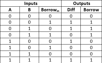
Figure 9 - Full subtractor truth table
It’s important to highlight that there are also other ways to construct the logic gates in the circuit to get the same truth table (AKA.. build a subtractor in this case), so the purpose of the circuits is to return the expected outputs from the truth tables.
If you want to go deeper into the subtractors I recommend this site , because there are many more details that I’m not going to cover here. After all, it would change the main topic.
Multiplier
First things first, the multiplication consists of multiple comparisons between the multiplicand and the multiplier, and the number of runs of the circuit depends on the binary bit/byte “size”.
For example:
Figure 10 - Binary multiplication example
Source: circuitdigest.com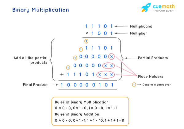
The comparison is made between each bit in the number and then we make a sum to resolve the problem. Technically this is also the way we do multiplication in school, but there the number type is decimal instead of binary.
Then we reach the complex part, the logic circuit, because theoretically we could just sum the multiplicand with itself multiplier times, but nothing is that simple, and I’m gonna show just a basic resolution for now. Then, in other posts, we’ll go deeper into how the ALU (part of the processor) actually makes operations…
So, continuing.. This is the logic circuit for a multiplier with 2-bit numbers
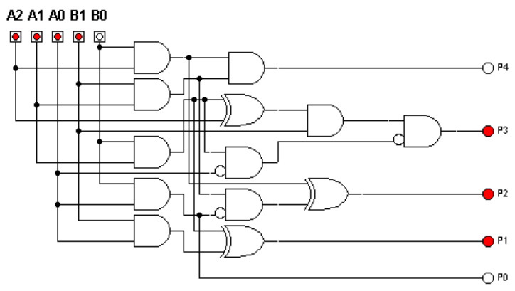
Figure 11 - 2-bit multiplier logic circuit
And here is the truth table:
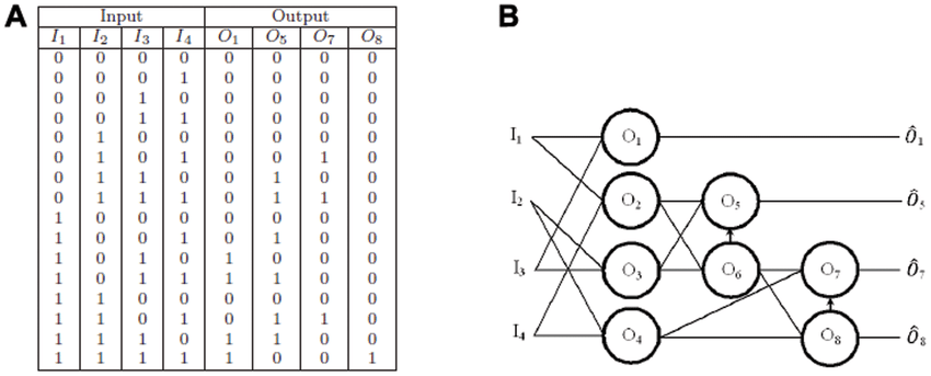
Figure 12 - Multiplier truth table
For each bit we have in the multiplication we get 2 more columns in the truth table and 2 more inputs/outputs, so in this setup things don’t scale very well, but it’s possible anyway
Divider
So, for the last one, we have the divider, which brings other implications like numbers from the rational field, and these numbers weren’t possible until now because we hadn’t gotten any number different from an integer. To solve this problem we could use floats (I’m gonna talk more about that in another post, but the technical name of the integer problem would be underflow)
The truth table is the simplest of all:
Figure 13 - Divider truth table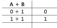
Because if we think about it a little, we reach the conclusion that division by zero is meaningless
So, to keep the same schema as the multiplier, we are gonna use the 2-bit division:
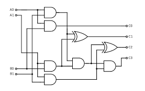
Figure 14 - 2-bit binary division circuit
It’s interesting, by the way, that only AND and EX-OR logic gates are necessary..
The inputs are both 2-bit numbers and the output C’s are the quotient, so if we expose the output somewhere we get the result (this is a simplified version of real-life usage, because for better approaches we probably would have to implement floating points and some other things, and I think that for now this is enough)